
Basic structure of camera module
I. Camera structure and working principle
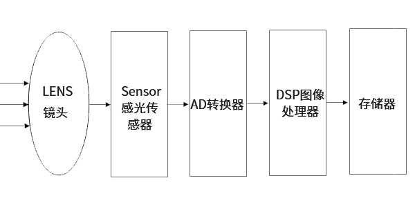
The scene is shot through the lens, the generated optical image is projected onto the sensor, and then the optical image is converted into electrical signal, which is converted into digital signal through analog-to-digital conversion. The digital signal is processed by DSP and then sent to the computer for processing, and finally converted into an image that can be seen on the phone screen.
Function of digital signal processing (DSP) chip: optimize the digital image signal parameters through a series of complex mathematical algorithms, and transfer the processed signals to PCs and other devices through USB and other interfaces. DSP structure frame:
1、 ISP(image signal processor)
1. ISP (image signal processor)
2、JPEG encoder
2. JPEG encoder
3、 USB device controller
3. USB device controller
There are two types of common camera sensors,
One is the CCD (Chagre Couled Device)sensor, that is, charge coupled device.
The other is CMOS (Complementary Metal-Oxide Semiconductor)sensor, that is, complementary metal oxide semiconductor.
The advantage of CCD lies in the good imaging quality, but the manufacturing process is complicated, the cost is high, and the power consumption is high. At the same resolution, CMOS is cheaper than CCD, but the image quality is lower than CCD. Compared with CCD, CMOS image sensor has lower power consumption. In addition, with the advancement of process technology, the image quality of CMOS has also been continuously improved. Therefore, the current mobile phone cameras on the market all use CMOS sensors.
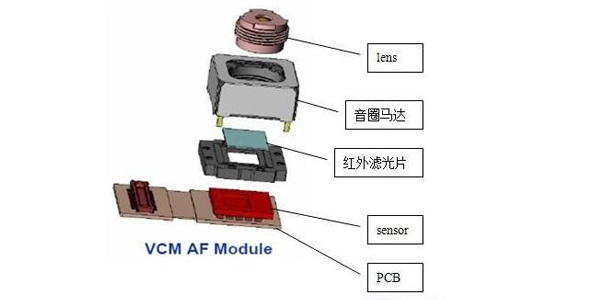
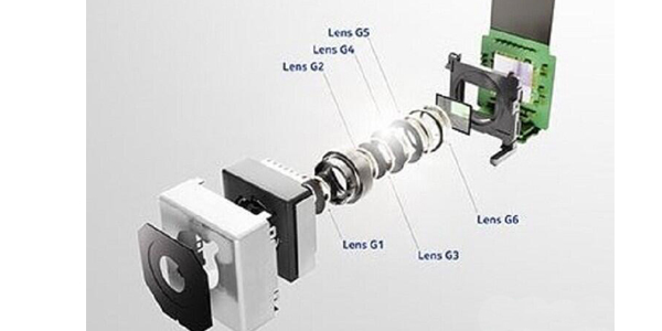
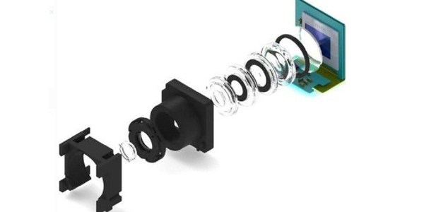
Simple structure of mobile phone camera
Lens: gather light and project the scene onto the surface of the imaging medium.
Image sensor: the imaging medium, which converts the image (light signal) projected by the lens onto the surface into an electrical signal.
Motor: drives the movement of the lens, so that the lens projects a clear image onto the surface of the imaging medium.
Color filter: The scene seen by the human eye is in the visible light band, and the image sensor can recognize the light band more than the human eye. Therefore, a color filter is added to filter out the excess light band, so that the image sensor can capture actual scenes seen by eyes.
Motor drive chip: used to control the movement of the motor and drive the lens to achieve autofocus.
Circuit board substrate: Transmit the electrical signal of the image sensor to the back end.
II. Related parameters and nouns
1. Common image formats
1.1 RGB format:
The traditional red, green and blue format, such as RGB565 and RGB888; the 16-bit data format is 5-bit R + 6-bit G + 5-bit B. G has one more bit because human eyes are more sensitive to green.
1.2 YUV format:
Luma (Y) + chroma (UV) format. YUV refers to the pixel format in which the luminance parameter and the chrominance parameter are expressed separately. The advantage of this separation is that it not only avoids mutual interference, but also reduces the chroma sampling rate without affecting the image quality too much. YUV is a more general term. For its specific arrangement, it can be divided into many specific formats.
Chroma (UV) defines two aspects of color: hue and saturation, which are represented by CB and CR respectively. Among them, Cr reflects the difference between the red part of the RGB input signal and the brightness value of the RGB signal, while Cb reflects the difference between the blue part of the RGB input signal and the brightness value of the RGB signal.
The main sampling formats are YCbCr 4:2:0, YCbCr 4:2:2, YCbCr 4:1:1 and YCbCr 4:4:4.
1.3 RAW data format:
The RAW image is the raw data that the CMOS or CCD image sensor converts the captured light source signal into digital signal. A RAW file is a file that records the original information of the digital camera sensor and some metadata (such as ISO settings, shutter speed, aperture value, white balance, etc.) generated by the camera. RAW is an unprocessed and uncompressed format and it can be conceptualized as “raw image coded data” or more vividly called “digital negative”. Each pixel of the sensor corresponds to a color filter, and the filters are distributed according to the Bayer pattern. The data of each pixel is output directly, namely RAW RGB data
Raw data (Raw RGB) becomes RGB after color interpolation.
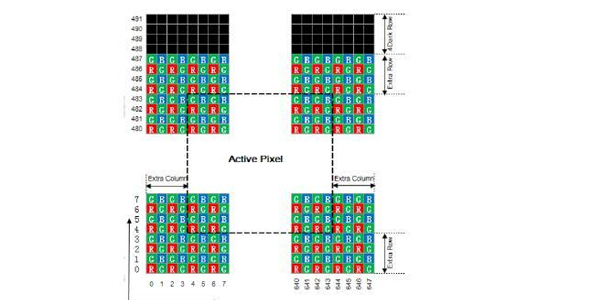
RAW format image example
2. Related technical indicators
2.1 Image resolution:
SXGA (1280 x1024), 1.3 megapixels
XGA (1024 x768), 0.8 megapixels
SVGA (800 x600), 0.5 megapixels
VGA (640x480), 0.3 megapixels (0.35 megapixels refer to 648X488)
CIF(352x288), 0.1 megapixels
SIF/QVGA(320x240)
QCIF(176x144)
QSIF/QQVGA(160x120)
2.2 Color depth (number of color bits):
256 color gray scale, 256 kinds of gray (including black and white).
15 or 16-bit color (high color): 65,536 colors.
24-bit color (true color): Each primary color has 256 levels, and their combination has 256*256*256 colors.
32-bit color: In addition to the 24-bit color, the extra 8 bits are used to store the graphic data of the overlapping layer (alpha channel).
2.3 Optical zoom and digital zoom:
Optical zoom: Zoom in/out of the object you want to shoot by adjusting the lens. It keeps the pixels and image quality basically unchanged, but you can take ideal image. Digital zoom: There is no zoom actually. It just takes from the original picture and zooms in. What you see on the LCD screen is enlarged, but the picture quality is not substantially improved, and the pixels are lower than the maximum pixels that your camera can shoot. The picture quality is basically unworthy, but it can provide some convenience.
2.4 Image compression method:
JPEG/M-JPEG
H.261/H.263
MPEG
H.264
2.5 Image noise:
It refers to the noise and interference in the image and appears as fixed color noise in the image.
2.6 Auto white balance:
Simply put: the restoration of white objects by the camera. Related concepts: color temperature.
2.7 Viewing angle:
It has the same principle as the imaging of the human eye, which is also known as the imaging range.
2.8 Auto focus:
Autofocus can be divided into two categories: one is ranging autofocus based on the distance between the lens and the subject, and the other is focus detection autofocus based on clear imaging on the focusing screen (sharpness algorithm).
Note: Zooming is to bring distant objects closer. Focus is to make the image clear.
2.9 Auto exposure and Gamma:
It is the combination of aperture and shutter. Aperture, shutter speed, ISO. Gamma is the response curve of the human eye to brightness.
III. Other camera structure
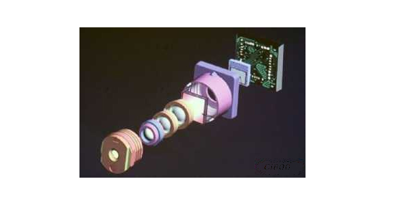
3.1 Fixed focus camera structure
3.2 Optical image stabilization camera structure
3.3 MEMS camera
Post time: May-28-2021